What a circuit diagram is, the difference between pictorial and schematic diagrams, why they matter in circuit design and the symbols and line styles they use.
 Onlitex Engineering Team2 min read

What is a circuit diagram?
A circuit diagram is a visual representation of an electrical circuit, using either basic images of parts or industry-standard symbols. Which symbols are used depends on the audience viewing the diagram. The two types of circuit diagram are called pictorial (using basic images) and schematic (using industry-standard symbols).
A schematic circuit diagram gives a visual representation of an electrical circuit to an electrician or engineer. A pictorial circuit diagram is used for a broader, less technical audience.
Purpose of circuit diagrams
Circuit diagrams are created as a blueprint of a circuit design. A circuit diagram provides a graphical representation of the arrangement of all the components in a circuit and the wiring between them. Technicians create circuit diagrams as a guide for implementing a circuit design or for communication.
Understanding circuit diagrams
A circuit diagram is a graphical visualization of an electrical circuit. It provides a schematic illustration that shows the relationships between the components in the circuit. The example below gives you an idea of what circuit diagram symbols look like.
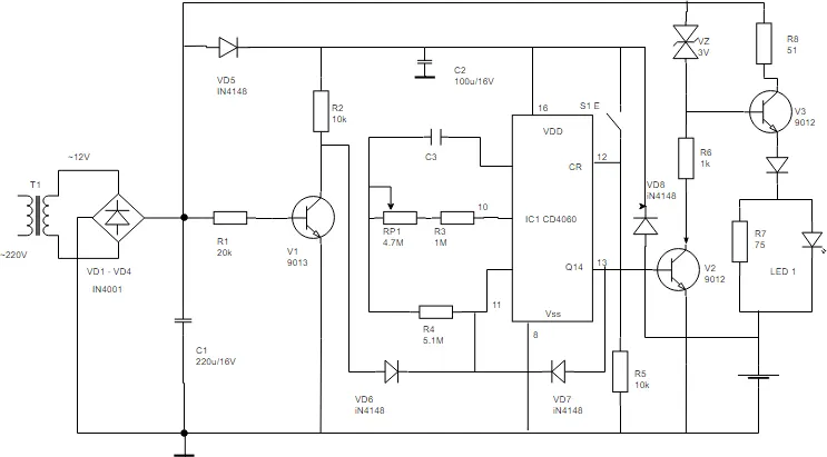
Circuit diagram symbols
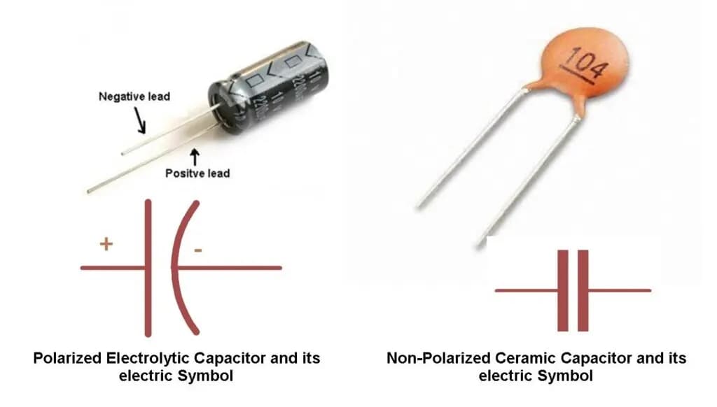
There are hundreds of different symbols that can be used in a circuit diagram. They include simple images of objects, such as a battery or a resistor, for a pictorial circuit diagram, or industry-standard symbols for objects such as capacitors or inductors.
Capacitor color code
Capacitance values, for example, are often marked with a color code, as shown below:
| Color | 1st digit | 2nd digit | Multiplier | Tolerance (±) over 10 pF | Tolerance (±) under 10 pF | Temperature coefficient |
|---|---|---|---|---|---|---|
| Black | 0 | 0 | 1 | 20% | 2.0 pF | 0 |
| Brown | 1 | 1 | 10 | 1% | — | -30 |
| Red | 2 | 2 | 100 | 2% | — | -80 |
| Orange | 3 | 3 | 1,000 | — | — | -150 |
| Yellow | 4 | 4 | 10,000 | — | — | -220 |
| Green | 5 | 5 | 100,000 | 5% | 0.5 pF | -330 |
| Blue | 6 | 6 | 1,000,000 | — | — | -470 |
| Violet | 7 | 7 | 10,000,000 | — | — | -750 |
| Gray | 8 | 8 | 0.01 | — | 0.25 pF | 30 |
| White | 9 | 9 | 0.1 | 10% | 1.0 pF | +120 to -750 / +500 to -330 |
| Gold | — | — | — | — | — | Bypass or coupling |
Line styles
As well as circuit diagram symbols, there is a series of line styles used to connect objects. Where lines cross, use line hops to show a wire crossover. It is important to understand who will be viewing the circuit diagram so that the correct types of symbols are used.
For more detail on common component symbols, see our guides to resistor, capacitor, diode and transistor circuit symbols.
- #circuit diagram
- #schematics
- #circuit symbols
- #PCB design