The key SMT steps for flexible printed circuits: fixing the FPC to a carrier, solder paste printing, placement, reflow profiling, inspection and depaneling.
 Onlitex Engineering Team3 min read
This article uses an ordinary carrier board as an example to explain the key points of surface mount technology (SMT) for flexible printed circuits (FPC). When a silicone board or magnetic fixture is used, fixing the FPC is much more convenient and no tape is needed, but the key points of printing, placement and soldering are the same.
1. Fixing the FPC
Before SMT, the FPC must first be accurately fixed to the carrier board. Note that once the FPC is attached to the carrier, the shorter the storage time before printing, placement and soldering, the better.
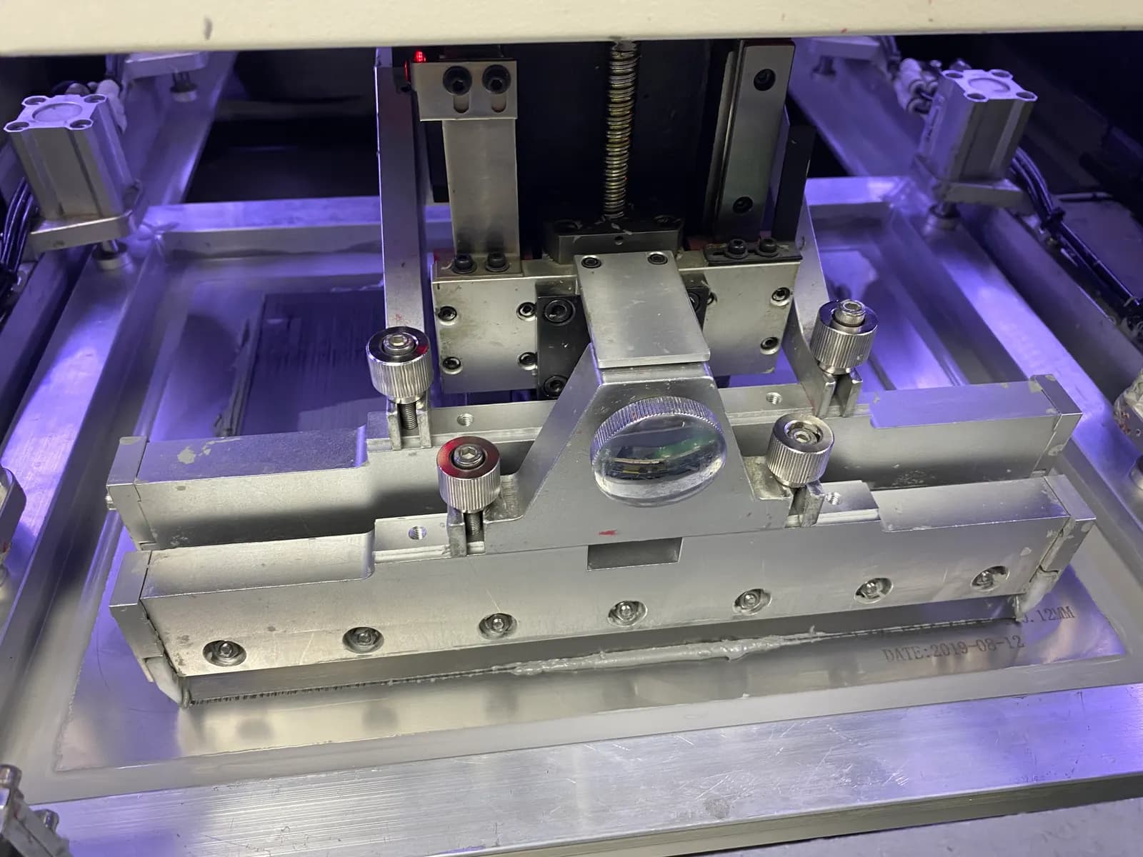
2. Solder paste printing on FPC
FPC has no special requirements for the composition of the solder paste. The solder ball size and metal content are chosen according to the fine-pitch ICs on the FPC. However, FPC places high demands on the printing performance of the solder paste, so the paste should have excellent properties. In terms of thixotropy, the solder paste should release easily from the stencil and adhere firmly to the surface of the FPC, without poor release, clogged stencil apertures or slumping after printing.
3. Component placement on FPC
Depending on the characteristics of the product, the number of components and the placement efficiency required, components can be mounted with medium- or high-speed placement machines.
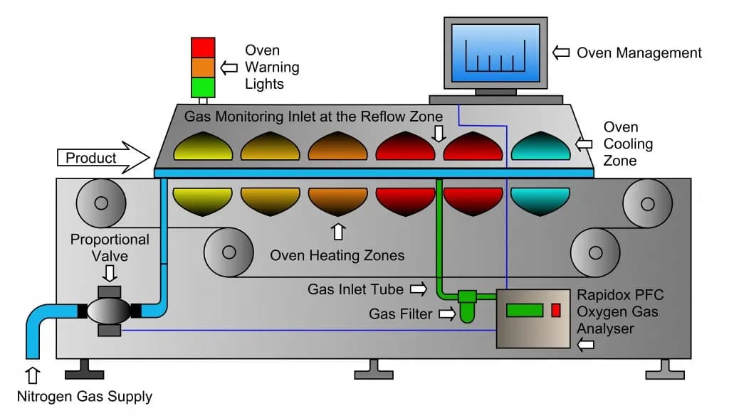
4. Reflow soldering of FPC
A forced hot-air convection infrared reflow oven should be used, so that the temperature across the FPC changes more evenly and poor soldering is reduced.
Temperature profile test method
A more reliable method is to place two FPC-loaded carrier boards in front of and behind the test board, using the actual board spacing from production. At the same time, components are mounted on the FPC of the test carrier board, and the temperature is measured using high-temperature solder wire: the probe is soldered to the test point, while the probe leads are secured to the carrier with high-temperature tape.
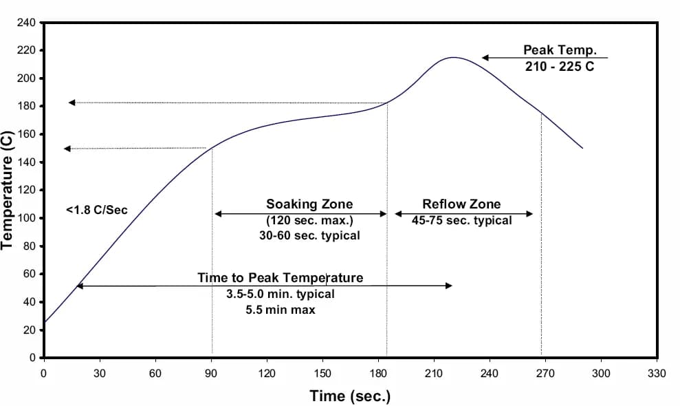
Setting the temperature profile
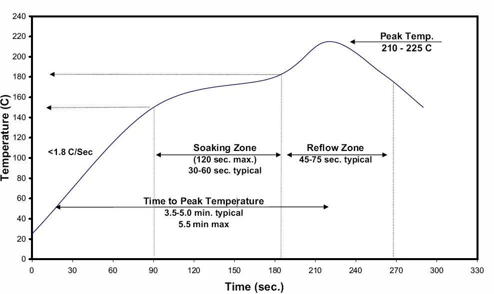
When adjusting the oven temperature, because the temperature uniformity of FPC is poor, it is best to use a preheat, soak and reflow temperature profile, as shown in the figure below.
5. Inspection, testing and depaneling of FPC
Because the carrier absorbs heat in the oven, especially an aluminum carrier, it is hot when it comes out. It is therefore best to add a forced cooling fan at the oven exit to help it cool down quickly.
The removed FPCs are visually inspected under a magnifying glass of 5× or more, focusing on residual adhesive on the surface, discoloration, solder on the gold fingers, solder beads, open IC pins and other soldering defects.
For mass production of shaped FPCs, a dedicated FPC punching and separation die is recommended, which can greatly improve working efficiency. The edges of punched FPCs are also neat and clean, and the internal stress generated during punching is very low, which effectively prevents solder joint cracking.
Conclusion
In the assembly and soldering of flexible PCBA, precise positioning and fixing of the FPC is the key point, followed by FPC pre-baking, printing, placement and reflow soldering. Strict production process management is also important. Operators must strictly follow every rule in the SOP, while engineers and IPQC should strengthen inspections, identify abnormal conditions on the production line promptly, analyze the causes and take the necessary measures to keep the defect rate of the FPC SMT line within a few dozen PPM.
- #FPC assembly
- #flexible PCB
- #SMT process
- #reflow profile