Surface-mount or through-hole? Compare cost, reliability, density and production speed to choose the right PCB assembly method for your product.
 Onlitex Engineering TeamUpdated 6 min read
Almost every electronic product is built with surface-mount technology (SMT), through-hole technology (THT), or a mix of both. The SMT vs through-hole decision affects your board size, unit cost, reliability and lead time, so it is worth understanding how each process works and where each one makes sense before you finalize your layout.
What is SMT assembly?
In SMT, components are placed directly onto pads on the surface of the board, with no leads passing through it. Parts range from tiny 0201 passives to large BGAs with hundreds of balls underneath.
The SMT process step by step
- Solder paste printing. A laser-cut stainless steel stencil, made from the paste layer of your Gerber files, is aligned to the board. A squeegee pushes solder paste through the apertures onto each pad. Stencil thickness and aperture design control how much paste each joint gets.
- Paste inspection. Many lines check paste deposits before placement, because most SMT defects start at the printing stage.
- Pick-and-place. Machines programmed from the centroid file pick parts from reels, trays or tubes and place them on the paste at high speed, using fiducial marks to correct for board position.
- Reflow soldering. The board passes through a multi-zone oven with a controlled profile: preheat, soak, a peak above the solder's melting point, then cooling. The profile is tuned to the board's thermal mass and the most sensitive components.
- Inspection. Automated optical inspection (AOI) checks for missing, shifted, tombstoned or bridged parts. Hidden joints under BGA, QFN and LGA packages need X-ray inspection.
For double-sided SMT, the side with lighter parts is usually reflowed first, then the board is flipped and the second side is printed, placed and reflowed.
Advantages
- Very high component density and smaller boards
- Fast, fully automated placement and lower cost per board
- Components on both sides of the board
- Better high-frequency performance thanks to shorter leads and lower parasitic inductance
- Most new components are only available in SMT packages
Limitations
- Joints are less resistant to heavy mechanical stress, such as repeated connector insertion
- Hidden joints (BGA, QFN) need X-ray inspection
- Fine-pitch parts are hard to rework by hand
- Requires a stencil and machine programming for each design
What is through-hole assembly?
In THT, component leads go through plated holes in the board and are soldered on the opposite side. The solder fills the barrel of the hole, creating a joint that is mechanically anchored through the board.
The THT process step by step
- Component insertion. Leads are inserted into the holes, by hand for most mixed boards, or by axial/radial insertion machines for high volumes of suitable parts.
- Soldering, by one of three methods:
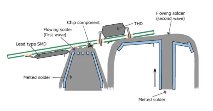
- Wave soldering: the board is fluxed, preheated and passed over a standing wave of molten solder that wets every exposed lead on the bottom side. It is fast and well suited to boards with many through-hole joints.
- Selective soldering: a small programmable nozzle solders individual joints or rows of pins. It is slower than wave, but it protects nearby bottom-side SMT parts and suits mixed-technology boards.
- Hand soldering: used for prototypes, small runs, heat-sensitive parts or touch-up.
- Lead trimming and cleaning, if required.
- Inspection. Visual inspection and AOI check fillets and solder bridges. IPC-A-610 also sets minimum vertical fill requirements for plated through-holes, which depend on the product class.
Advantages
- Strong mechanical bonds, ideal for connectors, switches and heavy parts
- Handles high current and heat well
- Easy to prototype, probe and rework
Limitations
- Takes more board space and requires drilling, which also blocks routing on inner layers
- More manual handling, so it is slower and costs more at volume
- Components on one side only in most practical builds
SMT vs through-hole at a glance
| Factor | SMT | Through-hole |
|---|---|---|
| Component density | High | Low |
| Cost at volume | Lower | Higher |
| Mechanical strength | Good | Excellent |
| Power handling | Good | Excellent |
| High-frequency performance | Better | Lower (longer leads) |
| Automation | Fully automated | Wave, selective or manual |
| Setup items | Stencil, placement program | Wave settings, selective program, fixtures |
| Inspection | AOI, X-ray | Visual, AOI |
| Rework | Harder for fine-pitch | Easier |
What drives assembly cost
The method itself is only part of the price. The main cost drivers are:
- Number of process steps. Single-sided SMT is the simplest flow. Double-sided SMT adds a second print-place-reflow pass. Adding THT adds insertion and a soldering step.
- Manual operations. Every hand-inserted or hand-soldered part adds labor and variability. A board with three connectors costs less to finish than one with thirty through-hole parts.
- Bottom-side SMT on a wave-soldered board. This may require selective soldering or a wave pallet that masks the SMT parts.
- Special inspection. BGA and QFN parts add X-ray checks.
- One-time setup. Stencils, programs and any fixtures are spread across the order quantity, so they matter most on small runs.
Design tips for each method
For SMT
- Use standard package sizes your manufacturer places routinely, and avoid mixing very small and very large parts where paste volume needs conflict.
- Add global fiducials, and local fiducials near fine-pitch parts.
- Keep components away from board edges and V-score lines.
- Balance copper on thermal pads and use via patterns that won't wick solder away from the joint.
For through-hole
- Size holes for the maximum lead diameter plus clearance for solder flow (check your fabricator's guidelines). Holes that are too tight block fill; holes that are too loose cause voids and weak joints.
- Use thermal relief connections to large copper planes so the barrel can reach soldering temperature.
- Keep all THT parts on one side where possible.
- For selective soldering, leave clearance around through-hole pins for the nozzle, and keep tall SMT parts away from those pins on the bottom side.
- For wave soldering, orient bottom-side parts to reduce shadowing, and ask your manufacturer for their wave-side design rules.
Consider SMT alternatives
Many connectors, inductors and even electrolytic capacitors are available in surface-mount versions, some with through-hole hold-down pegs for strength. Replacing a few THT parts can sometimes remove an entire soldering step. Our PCB design team can review these trade-offs during layout.
When to choose each method
Choose SMT when:
- Board space is limited or the product is small and light
- You are building at medium to high volume and want the lowest unit cost
- The design includes high-speed or RF circuits
- The components you need are only available in SMT packages
Choose through-hole when:
- Parts face mechanical stress: connectors, switches, terminals, heavy transformers
- Components carry high current or dissipate significant heat
- You need easy field repair or hand-built prototypes
The best of both: mixed-technology assembly
Most real products combine both. Logic, passives and ICs are surface-mounted for density and cost, while connectors, transformers and large electrolytic capacitors are through-hole for strength. A typical mixed-technology flow is:
- SMT on the top side (and bottom side, if used), with reflow
- AOI, plus X-ray for hidden joints
- Through-hole insertion
- Wave or selective soldering, then any hand soldering
- Final inspection, then inspection and testing such as ICT, flying probe or functional test
Where the components allow, pin-in-paste reflow can bring some through-hole parts into the SMT pass and remove a soldering step.
Conclusion
There is no universal winner in the SMT vs through-hole debate. SMT should be your default for density and cost; through-hole earns its place wherever strength, current or serviceability matter. Most products end up mixed, and good design choices keep that mix efficient to build.
At Onlitex, our four automatic SMT lines and dedicated wave soldering line handle SMT, THT and mixed boards, all assembled to IPC-A-610. Learn more about our PCB assembly service, or send us your design and our engineers will recommend the most cost-effective process.
FAQ
Is SMT cheaper than through-hole assembly?
For most designs, yes. SMT is highly automated, uses smaller parts and needs fewer drilled holes, so cost per board is usually lower — especially at volume.
When should I use through-hole components?
Use through-hole for parts that face mechanical stress or high current, such as connectors, large capacitors, transformers and power components.
Can one board use both SMT and THT?
Yes. Mixed-technology boards are very common. SMT parts are placed and reflowed first, then through-hole parts are soldered by wave or selective soldering.
What is the difference between wave and selective soldering?
Wave soldering passes the whole underside of the board over a wave of molten solder, which is fast but exposes every bottom-side feature. Selective soldering uses a small nozzle to solder individual through-hole joints, so it suits mixed boards with SMT parts on the bottom side.
Can through-hole parts go through the reflow oven?
Some can. With pin-in-paste (intrusive reflow), solder paste is printed over the holes and the through-hole part is reflowed with the SMT parts. The component must tolerate reflow temperatures, and the stencil and hole sizes must be designed for it.
- #SMT assembly
- #through-hole assembly
- #PCB assembly
- #DFM