Gerber, BOM, pick-and-place, STP and test specs — the exact files a PCB assembly manufacturer needs to give you an accurate quote in 24–48 hours.
 Onlitex Engineering TeamUpdated 6 min read
A fast, accurate PCB assembly quote depends almost entirely on the files you send. Missing or inconsistent data means back-and-forth emails, assumptions built into the price, and delays before production can start. This guide covers every one of the PCB assembly quote files a manufacturer needs, what each file should contain, and the common mistakes that slow quotes down, so you can get it right the first time.
Why complete files matter
An assembly quote is not just a parts list with a markup. To price a board, engineers need to know how many unique parts there are, how many placements per board, which components are fine-pitch or bottom-terminated (BGA, QFN, LGA), whether parts sit on one side or both, how many through-hole parts need wave, selective or hand soldering, and what testing is required. Each of those answers comes from a specific file. When one is missing, the quote either waits or includes a conservative assumption that may cost you more than necessary.
1. Gerber files (RS274X)
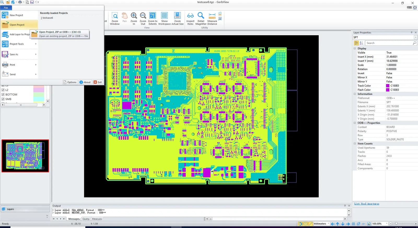
Gerber files describe each layer of the bare board. Send the complete set:
- Copper layers (top, bottom and every inner layer)
- Solder mask layers (top and bottom)
- Silkscreen (legend) layers
- Solder paste layers, which are used to cut the SMT stencil
- Board outline or mechanical layer
- Drill files
Extended Gerber (RS274X) is the standard format because apertures are embedded in each file. Avoid the obsolete RS274D format, which needs a separate aperture list and is easy to misread. If you design in tools such as Protel 99SE or P-CAD 2001, you can also include the native PCB file.
Layer naming
Different CAD tools use different file extensions. Many follow the Protel/Altium convention:
| Layer | Common extension |
|---|---|
| Top copper | .GTL |
| Bottom copper | .GBL |
| Inner layers | .G1, .G2 … or .GP1, .GP2 … |
| Top / bottom solder mask | .GTS / .GBS |
| Top / bottom silkscreen | .GTO / .GBO |
| Top / bottom paste | .GTP / .GBP |
| Board outline | .GKO or .GM1 |
If your files use other names, add a short README or a fabrication drawing that lists each file and its layer, plus the layer stack-up order. On multilayer boards, the stack-up is the one thing a manufacturer cannot safely guess.
Drill and NC files
Drill data is usually in Excellon format (.DRL, .TXT or .XLN). Make sure it includes:
- Plated and non-plated holes, either in separate files or clearly distinguished
- Tool sizes as finished hole diameters
- Units and number format that match the Gerbers, so holes line up with pads
- Slots and routed cut-outs, shown on the outline or mechanical layer
2. Bill of materials (BOM)
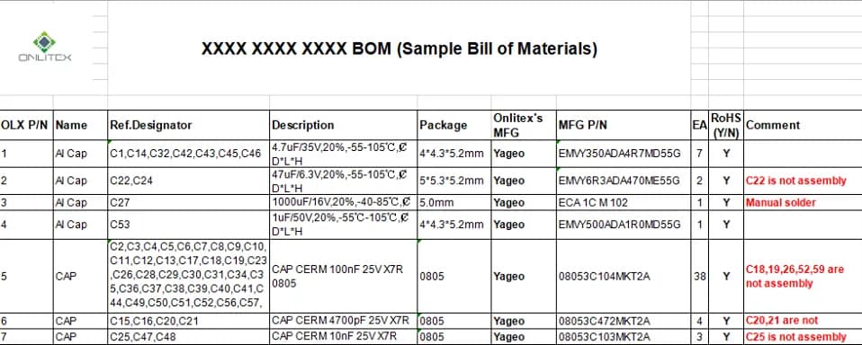
The BOM is the most important document for pricing. An Excel file is preferred, with one row per unique part and these columns:
| Column | Example |
|---|---|
| Line item | 1 |
| Reference designators | R1, R2, R5 |
| Quantity per board | 3 |
| Manufacturer | Yageo |
| Manufacturer part number | RC0603FR-0710KL |
| Description / value | 10kΩ 1% 0603 |
| Package / footprint | 0603 |
| Approved alternates | Optional |
| Notes | DNP, customer-supplied, etc. |
BOM best practices
- Use manufacturer part numbers, not distributor SKUs. A distributor order code ties pricing to one source and can be ambiguous across packaging options.
- Make quantities match designators. If a line lists five designators, quantity per board should be five.
- Mark do-not-populate (DNP) parts clearly rather than deleting them, so engineers know the pads are intentionally empty.
- List approved alternates for passives and common parts. This gives the sourcing team room to work when a part is short.
- Flag consigned parts. If you will supply some components yourself, say which lines.
- Keep the BOM revision in sync with the Gerber and centroid revision.
Clear manufacturer part numbers let the supply chain team price parts accurately and flag long-lead or end-of-life components before they become a problem.
3. Pick-and-place (centroid) file
The centroid file lists the position and orientation of every component and is used to program the SMT machines. A typical file is CSV, TXT or Excel with these columns:
- Designator (must match the BOM and silkscreen)
- X and Y position of the part center
- Rotation in degrees
- Side (top or bottom)
State the units (mm or mils) and the origin point. Rotation conventions differ between CAD libraries, so engineers will check orientation against the silkscreen and an assembly drawing. That is why a separate assembly drawing showing polarity marks, pin 1 locations and any special instructions is worth including.
4. 3D files (STP)
For box build or tight mechanical fits, STP files help engineers check component heights, connector positions and enclosure clearances. They are optional for a bare PCBA quote but valuable when the board goes into a housing.
5. Panelization notes
Small boards are usually assembled in a panel, which carries the boards through printing, placement and reflow. You do not have to panelize yourself. If you have no specific needs, send the single-board design and let the manufacturer propose a panel. If you do have requirements, include a panel drawing that shows:
- Number of boards per panel and their arrangement
- Separation method: V-score for straight edges, or tab routing (breakaway tabs, sometimes with "mouse bite" perforations) for irregular shapes
- Breakaway rails, tooling holes and global fiducials on the rails
- Local fiducials near fine-pitch parts, if your design uses them
Keep components, especially ceramic capacitors, away from V-score lines and breakaway tabs; flexing during depaneling can crack them.
6. Quantity and specifications
Tell us:
- Quote quantities, ideally several price breaks (for example prototype, pilot and production volumes)
- Expected annual volume, if known
- Board specifications: material, thickness, layer count, copper weight, solder mask color, surface finish
- Whether parts are turnkey, consigned or partially supplied
- Lead-free / RoHS requirements and the IPC-A-610 class you expect
- Any special requirements: conformal coating, programming, cleaning, labeling or packaging
7. Test documents
If you need testing beyond standard inspection, send your test specification, pass/fail criteria, any test fixtures and the firmware with programming instructions. This lets engineers include inspection and testing such as AOI, X-ray, ICT, flying probe or functional test in the quote and production plan from the start.
Common mistakes that delay a quote
- Revision mismatch. The BOM is Rev C but the Gerbers are Rev B, so designators no longer match.
- Missing paste layer or outline. Without them, the stencil and panel cannot be planned.
- Designators that don't match. Parts appear in the BOM but not the centroid file, or the other way round.
- Generic descriptions. "10uF capacitor" without voltage, dielectric, package or part number cannot be priced reliably.
- Obsolete or not-recommended parts. These trigger a search for alternates before the quote can be completed.
- No quantity. Price per board depends heavily on volume.
- Unclear supply model. It isn't stated which parts, if any, you will consign.
The complete PCB assembly quote files checklist
- Gerber files (RS274X) for all layers, with a layer list and stack-up
- Excellon drill files, plated and non-plated
- BOM in Excel with manufacturer part numbers, quantities and DNP marking
- Pick-and-place / centroid file with units and side
- Assembly drawing (recommended)
- STP 3D files (if available)
- Panel drawing (only if you have specific requirements)
- Quantities and board specifications
- Test documents and firmware (if testing is required)
Put everything in a single ZIP named with the project and revision, and you have done most of the work. Sending complete, consistent PCB assembly quote files is the simplest way to get an accurate price quickly. Learn more about our PCB assembly service, or see our guide to SMT vs through-hole assembly if you are still finalizing your design.
Ready to go? Send your files to Onlitex — there's no MOQ, and you'll usually receive a detailed quotation within 24–48 hours, or 2–3 working days for BOMs with more than 100 component types.
FAQ
Can I get a PCBA quote with only a BOM?
You can get a component cost estimate, but an accurate assembly quote also needs Gerber files and placement data so the manufacturer can assess board complexity and process steps.
What Gerber format should I send?
Extended Gerber (RS274X) is the industry standard. Include all copper, solder mask, silkscreen, paste and drill files, plus a board outline.
How long does a PCB assembly quote take?
At Onlitex, usually 24–48 hours after engineering review, or 2–3 working days for BOMs with more than 100 component types.
Do I need to panelize my board before requesting a quote?
No. If you have no specific panel requirements, send the single-board Gerbers and the manufacturer can propose a panel layout. If your product or test fixture needs a particular panel, include a panel drawing with the quote files.
Should the pick-and-place file include through-hole parts?
It helps. SMT machines only use the SMT entries, but including through-hole parts gives engineers a complete picture of the board and makes it easier to cross-check the BOM.
- #PCB assembly quote
- #Gerber files
- #BOM
- #PCBA